Large-diameter pipe cutting involves more than selecting a cutting machine. Oversized workpieces can be difficult to load, support, rotate, position, and cut accurately. Different materials, wall thicknesses, cutting geometries, and site conditions also require different equipment configurations.
HEAD CNC develops customized pipe cutting solutions around these real production challenges. By evaluating the workpiece, cutting process, handling method, motion system, and operating environment, we help customers determine an appropriate equipment structure and configuration for their application.
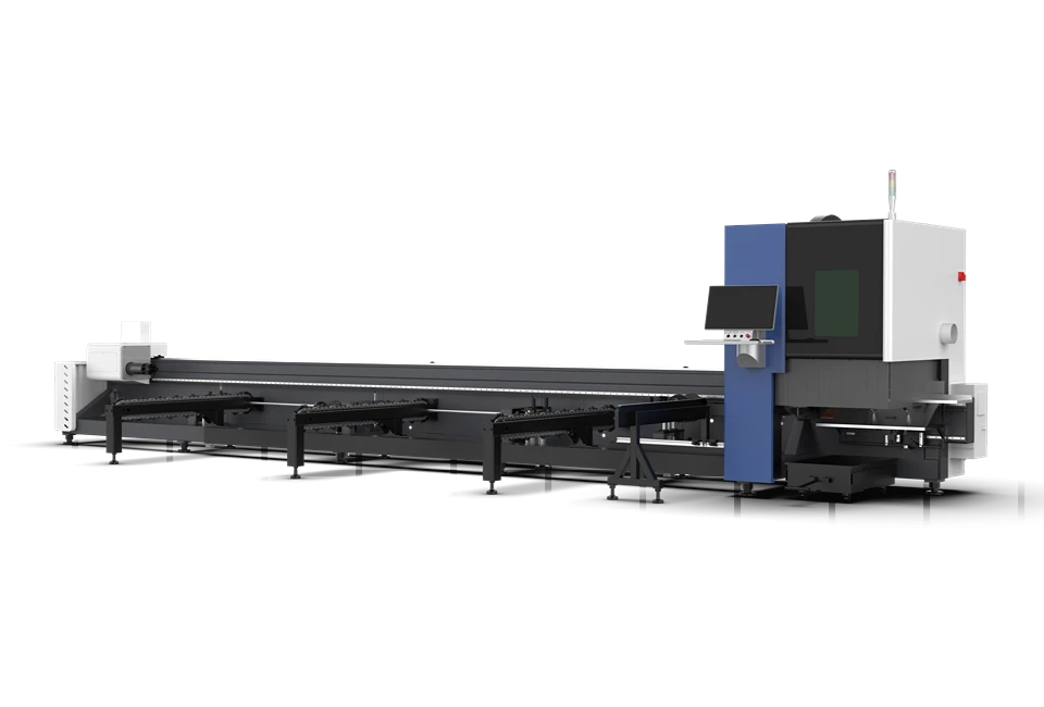
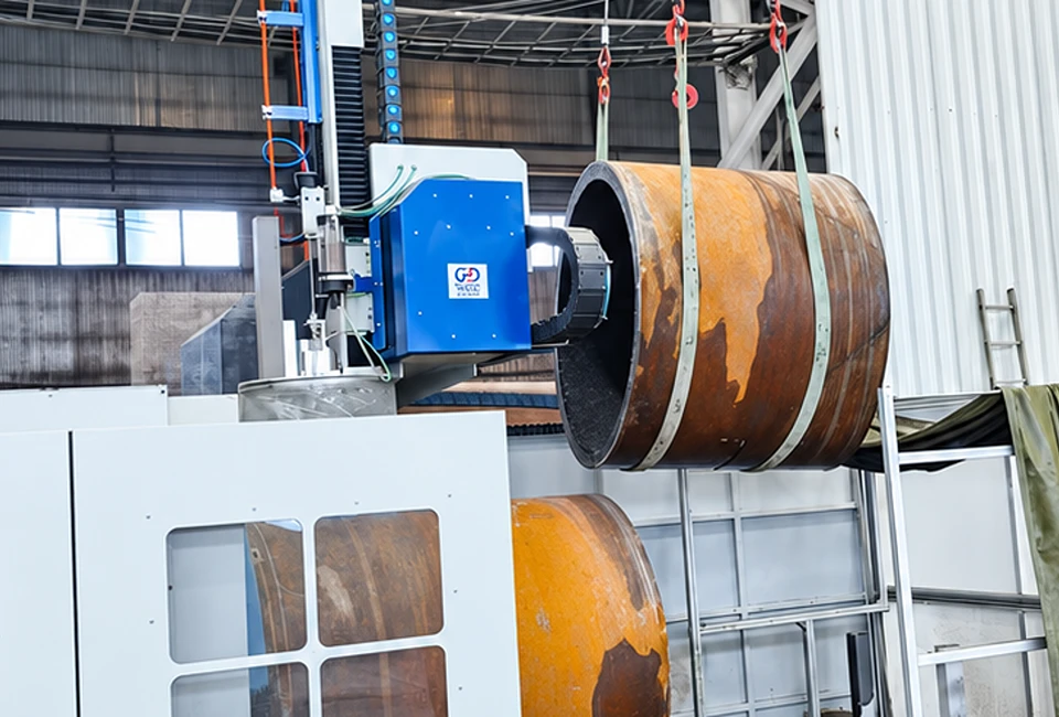
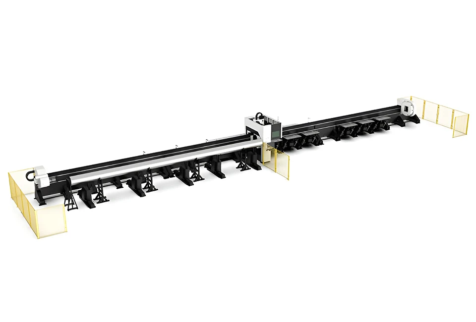
Designed for cutting large-diameter pipes that exceed the practical range of standard equipment. Heavy-duty support and positioning systems help accommodate long, heavy workpieces and maintain stability throughout the cutting process.
Coordinates pipe rotation with multi-axis cutting movement to support flexible processing of cylindrical workpieces. This integrated motion control helps maintain consistent positioning and enables more complex cutting operations.
Supports the processing of different pipe materials and wall thicknesses according to specific application requirements. Cutting methods and machine configurations can be evaluated based on material properties, pipe dimensions, and desired cutting results.
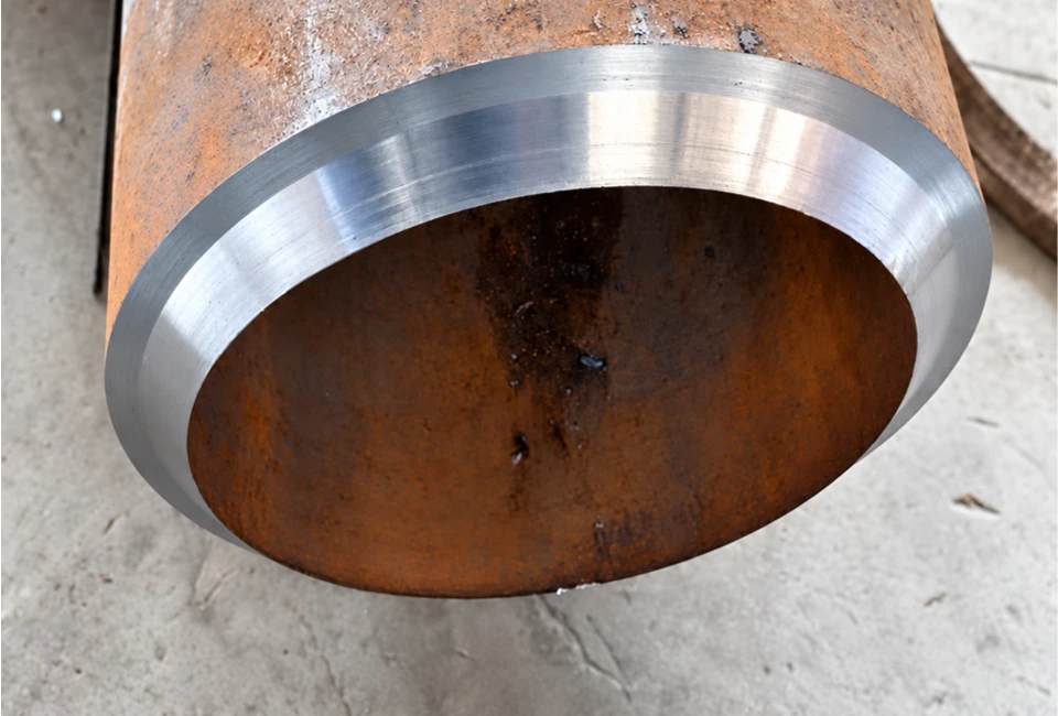
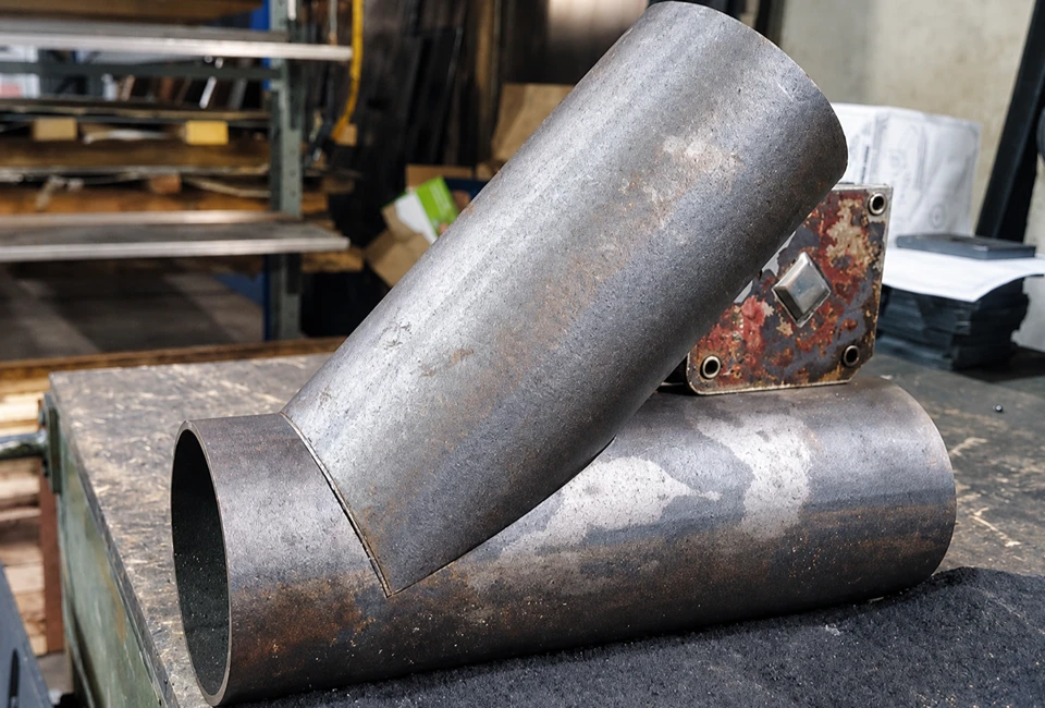
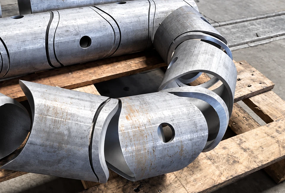
Supports a range of pipe cutting geometries, including circular openings, pipe-end cutting, bevels, and defined profiles. Multi-axis movement and controlled pipe rotation provide flexibility for customized pipe components and specialized processing tasks.
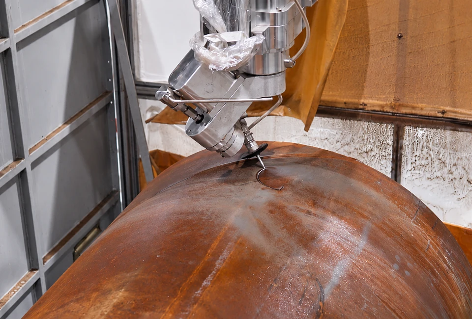
Evaluates portable and on-site cutting requirements for projects where transporting large pipes may be difficult. Suitable auxiliary systems, including abrasive handling, water collection, and other application-specific equipment, can be integrated to meet project needs.
Large pipes may exceed the available working area or handling range of standard machines. The required cutting system must be evaluated against the pipe diameter, length, available installation space, and loading method.
Heavy pipes require a suitable support arrangement to control movement during cutting. Depending on the application, this may involve support rollers, clamping devices, rotary systems, or customized fixtures.
Large-diameter pipes may be made from carbon steel, stainless steel, FRP/GRP, or composite materials. Material assessment and sample testing help determine the appropriate cutting process.
Pipe cutting may involve circumferential cuts, openings, end trimming, bevels, intersecting profiles, irregular contours, or sample preparation. Coordinated CNC motion, rotary axes, and fixtures help achieve the required geometry.
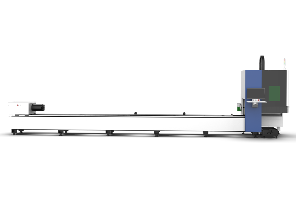
The project required a pipe cutting setup capable of handling heavy workpieces while maintaining stable positioning during rotary cutting. The main engineering considerations were how to support the pipe, secure it during processing, and coordinate pipe rotation with the cutting head. A conventional flat cutting table alone could not provide the complete handling and rotary-cutting arrangement required for this type of application.
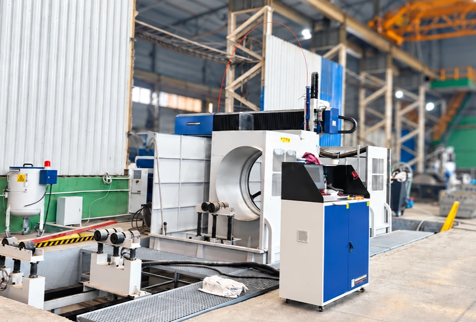
HEAD configured the SP-C HEAD3020SA around a 5-axis CNC cutting system, a high-strength hollow rotary system, synchronized dual-motor drive, a three-jaw chuck, and adjustable roller support. The rotary system has a rated maximum load capacity of up to 5,000 kg, while full closed-loop servo control supports precise positioning during processing. The published machine specifications include ±0.1 mm cutting accuracy and ±0.03 mm/500 mm repositioning precision.
By integrating pipe support, clamping, rotary movement, and CNC cutting into one workstation, the solution provides a coordinated setup for heavy pipe processing and defined cutting profiles.
HEAD evaluates the complete cutting process rather than selecting equipment based on pipe diameter alone. The proposed system is developed around the workpiece, required cutting operations, handling conditions, and production goals.
We review the pipe material, dimensions, wall thickness, weight, required geometry, and target cutting result. For applications involving composite or multilayer pipes, the material structure and expected edge condition are also considered.
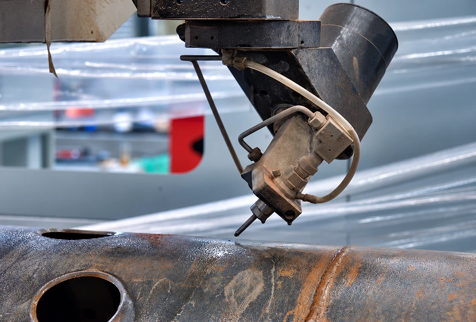
Waterjet cutting uses a high-pressure water stream, with abrasive added when required, to remove material without relying on the concentrated heat of conventional thermal cutting.
It can be considered when low thermal input, material versatility, or complex cutting paths are important. Its suitability must still be evaluated against the material, thickness, cutting speed, edge-quality requirements, and operating costs.
Depending on the application, HEAD can evaluate different system approaches.
Gantry-Type System: Suitable for projects requiring a defined working envelope and coordinated cutting-head movement around a stationary or supported workpiece. Dimensions, travel, support arrangements, and available motion axes are determined by the project.
Robotic Cutting System: May be considered for applications requiring flexible tool orientation, access to complex geometries, or integration with dedicated workpiece fixtures. Reach, payload, positioning requirements, and motion programming must be evaluated for the actual project.
Mobile or On-Site Cutting System: May be considered when the pipe or structure is difficult to move to a stationary machine. The proposed arrangement depends on surface conditions, access, attachment method, workpiece geometry, and site safety requirements.

The handling system may incorporate support rollers, clamping devices, a rotary axis, customized fixtures, or other positioning mechanisms.
The objective is to maintain suitable workpiece support and controlled movement throughout the cutting process.
Depending on the selected configuration, the solution may include:
– High-pressure waterjet pump
– Cutting head and CNC motion system
– Rotary drive and workpiece support
– Abrasive delivery system
– Abrasive removal system
– Water collection and treatment arrangements
– CAM software and cutting-path preparation
– Customized fixtures and auxiliary equipment
The final equipment list is determined by the application and confirmed technical requirements.
Where required, sample cutting and engineering evaluation can be used to assess the proposed process before finalizing the configuration.
The validation plan should reflect the customer’s actual material, dimensions, cutting geometry, and required result.
Depending on the selected equipment configuration and validated application, the solution may be developed for